Fire Alarm Wiring Diagram 5th Grade
Wire resistance ratings to use for wire length calculations 75. 4000-06 Fire alarm wiring and power sources.
 Errors In Connection Of 3 Pin Plug Physics Notes Learn Physics Connection
2007 NFPA 72 68562 Limits the number of supervisory devices in a single zone to 20.

Fire alarm wiring diagram 5th grade. Consult the appropriate installation sheet for wiring details. My customer is ok with the system having to have a. A wiring diagram is a streamlined traditional photographic depiction of an electric circuit.
5 TM Diagrams are for reference only. End-of-Line Resistors may be mounted in a properly identified common termination box or inside the fire alarm systems. Hi I have been asked to install a Grade A LD2 fire alarm for a customer of mine.
Collection of fire alarm wiring diagram pdf. An automatic fire alarm systemtypically made up of smoke detectors heat detectors manual pull stations audible warning. Electrical wiring and power sources serving fire alarm systems shall be installed in accordance with this section.
It is a standard 3 bed house with bedroom up top in the loft conversion making it 3 floors bathroom kitchen and lounge. Integrating Fire Alarm Control Using Direct Wiring The door access control reader and the electric lock can be wired to the fire alarm in a number of different ways. A wiring diagram is a simplified conventional pictorial representation of an electric circuit.
A78-2286-09 CURRENT RATING MAXIMUM VOLTAGE LOAD DESCRIPTION APPLICATION 3 A 2 A9 A9 A5 A 1 A5 A7 A 30 VDC 30 VDC 110 VDC 125 VAC 30 VDC 30 VDC 125 VAC 75 VAC Resistive Resistive Resistive Resistive Inductive LR5ms Inductive LR2ms Inductive PF35 Inductive PF35 Non Coded Coded Non Coded. This section shall apply to the alteration of existing buildings in accordance with Section 10143 of Title 28 of the New York City Administrative Code and to all new. A Cables used for the mains supply to smoke alarms and any heat alarms and any interconnecting wiring between all smokeheat alarms may comprise any cable suitable for domestic mains wiring.
Variety of fire alarm installation wiring diagram. Wiring diagrams shall be based on the project floor plans with devices and proposed conduit routing. 2007 NFPA 72 68552 Limits the number of waterflow switches in a single zone to 5.
The line item for the 030 Ampere16AWG entry is shown as 150 feet in Table 5 of the FA-1000 installation manual. We have converted the 229 meter entry on the line next to it to reflect the corrected Imperial measurement of 751. Difference Between Conventional and Addressable Fire Alarm.
Of course none of this happens quickly. Smoke and heat alarms that are to be. The conductor composition for each conduit section shall be provided.
LIST OF TABLES REFERENCES Circuit Reference Table - Fireshield 9 Circuit Reference Table - QuickStart QS1 QS4 QSC 18 Circuit Reference Table - EST3 22 Table A-1. Minimum Grade and Category of system to be installed. 2007 NFPA 72 Annex A4466 Suggests that the maximum number of square feet in a single zone be limited to no more than 22500.
Relay module wiring diagram. Wiring Diagram of Heat Detector in Home AC Conventional Fire Alarm System. In the 2016 NFPA 72 National Fire Alarm and Signaling Code a new class of pathways was addedClass N for network.
165 Recommendations for wiring in Grade D and Grade E systems The following recommendations are applicable. And connecting wiring of entire fire alarm system. In a conventional fire alarm system all devices such as detectors sounders and call points are connected to the control panel through separate wire or cable instead of shared one.
We can use a relay to drop power to the electric lock or use an IP device that drops power using the network connection or add a power control box that drops power when the fire. It reveals the elements of the circuit as simplified forms and the power and signal connections between the devices. Variety of notifier fcm 1 wiring diagram.
This has been specified by the council. Refer to BS 5839 for full details Installation of fire alarm systems Power supplies. The distance and route for each NAC Notification Appliance Circuit shall be shown.
It reveals the parts of the circuit as streamlined forms and the power as well as signal links in between the tools. Include wiring and riser diagrams. A wiring diagram is a simplified conventional pictorial depiction of an electrical circuit.
2 FireLite SLC Wiring Manual PN 51309R2 3192019 Fire Alarm Emergency Communication System Limitations While a life safety system may lower insurance rates it is not a substitute for life and property insurance. Performance shall be based upon wiring Class Note the old Class Style has been replaced with Class only Alarms must activate NACs and Control circuits within 10 seconds Troubles Opens Grounds must be reported within 200 seconds No more than 5 Waterflow devices and no more than 20 Supervisory devices per IDC. When a contractor wants to connect new equipment to a fire alarm system the equipment must be allowed by NFPA 72 and in most cases be listed for fire alarm usage.
Electrical wiring serving fire alarm systems shall be installed in accordance with this rule. The minimum Grade and Category of fire detection and alarm system for protection of life in typical dwellings is given in the Table below Part of Table 1 of BS 5839-6. Where Article 760 of the electrical code make reference to the installation of wiring and equipment as required by RS 17-3 RS 17-3A RS 17-3B and.
4000-06 Fire alarm wiring. 4 Reduce the risk of false alarms with the Gent sensor application guide 4 Stage 5 Choice and siting of alarm sounders and visual alarms 4 Stage 6 Control equipment power supplies 4 Installation Wiring 4 Outline responsibilities of the Installer 4 Types of cable and where to use them 4 Other aspects in regard to installation practice. It shows the parts of the circuit as streamlined shapes as well as the power as well as signal connections in between the gadgets.
 Diagram Ham Radio Page Industrial Latching Relay Wiring 5 Pin 4x4 Autocamper Fiskeri
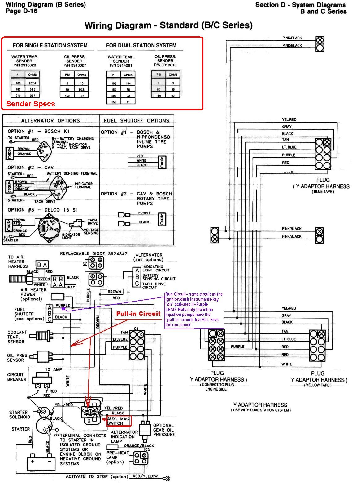 6bta 5 9 6cta 8 3 Mechanical Engine Wiring Diagrams
 City Video Surveillance Video Surveillance Surveillance Home Security Systems
 Wiring Diagram For Fire Alarm System With Schematic Of Fire Alarm System Fire Alarm Diagram
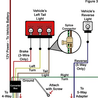 Troubleshooting 4 And 5 Way Wiring Installations Etrailer Com


